


![SoftPro Chlorine+ Carbon Whole House Water Filter to Remove PFAS, Chlorine, Chloramine & Pesticides [City Water Filters Series]](http://www.softprowatersystems.com/cdn/shop/files/SoftPro_Whole_House_Carbon_Filter_with_Spin_Down_Water_Filter.webp?v=1780515157&width=140)
![SoftPro Iron Filter - Iron Master AIO - Best Iron Filter for Well Water [Air Injected Water Filter / Katalox]](http://www.softprowatersystems.com/cdn/shop/files/SoftPro_AIO_Iron_Master_Iron_Filter_Main.webp?v=1772123747&width=140)


SOFTPRO
PH NEUTRALIZER
CALCITE FILTER
INSTALLATION GUIDE

Please read this manual carefully before attempting installation.
- This system and its installation must comply with state and local regulations. Check with your local public works department for plumbing and sanitation codes. If local codes conflict with this manual, local codes must be followed.
- For installations in Massachusetts, Massachusetts Plumbing Code 248 CMR shall be adhered to. Consult a licensed plumber for installation of this system.
- This water filter is designed to operate at pressures between 30 psi and 125 psi. If water pressure exceeds the maximum, a pressure-reducing valve must be installed. Pressure above 70 psi is not recommended, as it may damage seals, plumbing, and fixtures.
- This unit operates at temperatures between 40°F and 110°F (4°C – 43°C). Do not use this water filter on hot water supplies.
- Do not install this unit where it may be exposed to wet weather, direct sunlight, or temperatures outside the specified range unless protective measures are taken.
- Avoid pinched O-rings during installation by applying the provided NSF-certified lubricant to all seals.
- Filters are commonly exposed to iron, manganese, sulfur, and sediment. Damage to pistons, seals, or spacers within the control valve caused by these conditions is not covered under warranty.
- Annual inspection and servicing of the control valve is recommended. Cleaning or replacement of pistons, seals, and spacers may be required depending on water conditions. An Annual Maintenance Kit (Part #60010307) is available.
- Do not use water that is microbiologically unsafe without adequate disinfection before or after this system.
- The manufacturer reserves the right to make product improvements that may differ from the specifications and descriptions stated, without obligation to update previously manufactured products.
- This publication reflects information available at the time of printing. Ongoing design refinements may result in changes not included here.
Quality Water Treatment, Inc. reserves the right to change the specifications referred to in this literature at any time, without prior notice.
NOTE:
Do not remove or destroy the serial number. It must be referenced on request for warranty repair or replacement.
CAUTION!
Do not use where the water is microbiologically unsafe or with water of unknown quality without adequate disinfection before or after the unit.
Applies to private well or surface water applications only.
NOTICE: THIS PRODUCT HAS A LIMITED WARRANTY. BY INSTALLING AND OR USING THIS PRODUCT, YOU WAIVE CERTAIN LEGAL RIGHTS INCLUDING THE RIGHT TO SUE OR CLAIM COMPENSATION IN THE EVENT OF PROPERTY DAMAGE, INJURY, AND OR DEATH.
BEFORE INSTALLATION
All government codes and regulations governing the installation of these devices must be observed. Check your water hardness.
WARNING!
ELECTRICAL SHOCK HAZARD! UNPLUG THE UNIT BEFORE REMOVING THE COVER OR ACCESSING ANY INTERNAL CONTROL PARTS.
CAUTION!
The unit should be depressurized before installing or replacing media.
COPPER PIPES - GROUNDING STRAPS:
If the ground from the electrical panel or breaker box to the water meter or underground copper pipe is tied to the copper water lines and these lines are cut during installation of the Noryl bypass valve and/or poly pipe, an approved grounding strap must be used between the two lines that have been cut in order to maintain continuity.
The length of the grounding strap will depend upon the number of units being installed and/or the amount of copper pipe being replaced with plastic pipe.
In all cases where metal pipe was originally used and is later interrupted by poly pipe or the Noryl bypass valve or by physical separation, an approved ground clamp with no less than #6 copper conductor must be used for continuity, to maintain proper metallic pipe bonding.
CAUTION: If the plumbing system is used as the ground leg of the electric supply, continuity should be maintained by installing ground straps around any non-conductive plastic piping used in installation. Check your local electrical code for the correct clamp.
DRAIN LINE INFORMATION:
Waste connections or drain outlets shall be designed and constructed to provide for connection to the sanitary waste system through an air gap of 2 pipe diameters or 1 inch (22 mm) whichever is larger.
Never insert a drain line directly into a drain, sewer line, or trap. Always allow an air gap between the drain line and the wastewater to prevent the possi-bility of sewage being backsiphoned into the softener.
WATER PRESSURE INFORMATION:
Applies to private well or surface water applications only. If a severe loss in water pressure is observed when the Softener unit is initially placed in service, the softener tank may have been laid on its side during transit. If this occurs, backwash the softener to “reclassify” the media.
Check Your Water Pressure and Pumping Rate - Two water system conditions must be checked carefully to avoid unsatisfactory operation or equipment damage:
• Minimum water pressure required at the Softener tank inlet is 30 psi. • The pumping rate of your well pump must at least equal the required backwash flow rate of your model.LOCATE WATER TREATMENT EQUIPMENT CORRECTLY:
Select the location of your softener tank with care. Various conditions which contribute to proper location are as follows:
- Locate the softener as close as possible to the water supply source.
- Locate the softener as close as possible to a drain.
- Locate the softener in the correct relationship to other water conditioning equipment.
- The softener should be located near the supply line before the water heater. Temperatures above 120°F can damage softeners.
- Do not install a softener in a location where freezing temperatures may occur. Freezing can cause permanent damage and will void the factory warranty.
- Install a bypass for treated water when the water source is a community or public supply, or when bypassing water used for geothermal heat pumps, lawn sprinklers, outbuildings, or other high-demand applications.
- Keep the softener out of direct sunlight. Heat from the sun may soften and distort plastic components.
- Determine the best location by considering access to water supply lines, a drain line, and a 120-volt AC electrical outlet. Subjecting the Filter to freezing or temperatures above 43°C (110°F) will void the warranty.
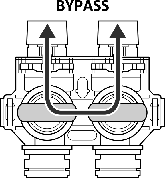
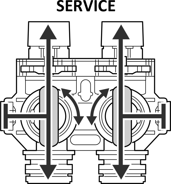
MANUAL WATER BYPASS:
In case of an emergency such as filter mainte-nance, youcan isolate your water filter from the water supply using the bypass valve located at the back of the control. In normal operation the bypass is open with the ON/OFF knobs in line with the INLET and OUTLET pipes. To isolate the filter, simply rotate the knobs clockwise indicated by the word BYPASS and arrow) until they lock.
You can use your water related fixtures and appli-ances as the water supply is bypassing the filter. However, the water you use will be hard. To resume treated service, open the bypass valve by rotating the knobs counterclockwise.
Please make sure bypass knobs are fully opened during service, otherwise the unsoftened water could bypass through the valve.

You are now ready to install your new
water softener system.
GENERAL INSTRUCTIONS
Below are the installation instructions to get you up and running in no time.
We highly recommend that you follow along in our simple installation videos.
Typical Install Times:
- 3 hours for a Handyman/ Plumber
- 4 hours for DIY
Tools Required:
- Flathead screwdriver
- Phillips head screwdriver
- Tongue-and-groove pliers (e.g., Channellock)
- Adjustable wrench
- Pipe cutter or hacksaw (as applicable)
Additional Parts (as applicable)
- Drain tubing: 1/2” ID vinyl tubing and 1/2” hose clamp (length sufficient to reach the drainpipe)
- Drainpipe connection and air gap fittings
- Inlet and outlet connection plumbing items
- Hose bibs and fittings (optional, but recommended)
For Copper, PEX, and CPVC pipes (as applicable):
- Fittings (Optional Quick-connect Hose Kit, or other quick-connect fittings. i.e. SharkBite)
For Copper, PEX, and CPVC pipes (as applicable):
- Electrical grounding strapping, if this new install will cut/ separate any existing copper pipes.
For PVC Pipes (as applicable):
- PVC Primer & glue, Teflon tape, pipe and fittings
- Note: The optional Quick connect Hose kit does not work on PVC pipes.
1) Is it OK if some items are delivered on their side or upside-down?
Yes, it is OK. If your shipment, boxes, or other items are delivered on their side or upside-down, do not be alarmed. Our team takes additional precautions to ensure your system is properly protected. Simply turn the shipment or box right-side up and unpack it.
2) What if there is damage to the exterior of the shipment or boxes?
We’ve got your back. If you notice visible damage to the exterior of the boxes, take photos and/or video of the damage before unpacking. Box damage does not necessarily mean the system is damaged. Continue unpacking and inspect the system carefully.
3) After unpacking, what if there is damage to the valve, tank, or other equipment?
We’ve got you. If you find visible damage to any parts, take photos and/or video immediately and send them to us. Replacement parts will be shipped to you promptly.
4) After unpacking, what if there is a missing item?
No worries. If any parts are missing, please contact us and we’ll help get everything set up properly.
Contact Support:
Web link: https://qualitywatertreatment.com/support
Email Address: Help@QualityWaterTreatment.com

ITEMS INCLUDED
NOTE:
Small parts are placed in the small parts bag inside the brine tank. Please keep in the bag until ready to install. (Let's not lose them....)
1) SoftPro Control Valve (packed inside the brine tank)
2) Mineral Tank with preloaded media and preinstalled distributor tube
3) Diffusion plate
4) Bypass valve
5) 1” connectors (qty. 2)
6) Funnel

NOTE:
Media is pre-loaded in the filter tank.

If you have additional water treatment filters (i.e. whole house filter, iron filter or pH neutralizer), those systems should always be installed before the water softener.
The water softener is the final treatment systems in your complete water treatment. (The exception is for a UV Disinfection System, which will be placed after the water filter.)
You are now ready to install your new water filter system.
GENERAL WATER SOFTENER TREATMENT SETUP
The following shows common setup.
These system setups include optional additional filter options.
WELL WATER TREATMENT SETUP

METAL PIPE GROUNDING GENERAL INFORMATION

Do you have existing copper water pipes?
Prior to installing the water filter, whenever metal piping is interrupted by poly pipe, a bypass valve, or physical separation, an approved ground clamp with no less than a #6 copper conductor must be installed to maintain proper metallic pipe bonding.
Refer to your local building code for grounding and bonding requirements.
CAUTION:
If the grounding from the electrical panel or breaker box to the water meter or underground copper pipe is connected to copper water lines, and these lines are cut during installation of the Noryl bypass valve and/or poly pipe, an approved grounding strap must be installed across the separated sections to maintain grounding continuity.
The required length and size of the grounding strap will depend on the number of units being installed and/or the amount of copper piping being replaced with plastic piping.
DRAIN CONNECTION GENERAL GUIDE
NOTE:
Do not remove the pre-installed drain port hose barb fitting from the SoftPro control valve.
Refer to the appropriate drain type.
This guide is intended for as a general reference. Your specific installation may vary from this guide.
NOTE:
Proper draining function may require an adequate air gap to prevent the possibility of wastewater being back-siphoned into the treatment system.