


![SoftPro Chlorine+ Carbon Whole House Water Filter to Remove PFAS, Chlorine, Chloramine & Pesticides [City Water Filters Series]](http://www.softprowatersystems.com/cdn/shop/files/SoftPro_Whole_House_Carbon_Filter_with_Spin_Down_Water_Filter.webp?v=1780515157&width=140)
![SoftPro Iron Filter - Iron Master AIO - Best Iron Filter for Well Water [Air Injected Water Filter / Katalox]](http://www.softprowatersystems.com/cdn/shop/files/SoftPro_AIO_Iron_Master_Iron_Filter_Main.webp?v=1772123747&width=140)


REVERSE OSMOSIS SYSTEM
INSTALLATION AND SERVICE GUIDE

Please read this manual carefully before attempting installation
Thank you for choosing SoftPro Water Systems.
You now own the finest water filter in America.
Your Reverse Osmosis (RO) System has been tested to ensure it will operate correctly. The following periodic maintenance is recommended so your system will provide years of trouble-free service:
Filter Replacement Schedule:
(depends on usage and water quality)
- Sediment and Carbon pre-filters and post-filters ... 12 months
- RO Membrane ... 12 months
- Alkalizing post-filter ... Typically 24 months
NOTICE: THIS PRODUCT HAS LIMITED WARRANTY. BY INSTALLING AND OR USING THIS PRODUCT, YOU WAIVE CERTAIN LEGAL RIGHTS INCLUDING THE RIGHT TO SUE OR CLAIM COMPENSATION IN THE EVENT OF PROPERTY DAMAGE, INJURY, AND OR DEATH.
The following tools may be necessary, depending on each particular installation:
- Power drill with appropriate drill bit types (1/4” and 3/8” sizes)
- Phillips head screwdriver
- 6” adjustable wrench
- Hammer and center punch
- Plastic tubing cutter or scissors
- Additional plumbing connections as required (not included)
- Optional ice maker fittings as required (tee, shut-off valve; not included)
The following components make up your reverse osmosis system:
Prefilter #1 (Sediment Filter)
Melt-blown polypropylene filter that removes larger particles such as dirt, rust, and sediment.
Prefilter #2 & #3 (if applicable)
10-micron carbon block filters that remove chlorine and chemical contaminants from the feed water and protect the RO membrane.
Reverse Osmosis Membrane
Thin Film Composite membrane that reduces dissolved minerals, metals, and salts. During this process, harmful compounds are separated by the membrane and flushed to the drain.
Postfilter
A coconut shell activated carbon postfilter provides a final polish, removes tastes and odors, and delivers great-tasting water.
RO Module
The main component that houses the prefilters, membrane, and postfilter. A mounting bracket is included for installation under a sink or in a basement.
Storage Tank
Holds purified RO water and keeps it ready for use.
Automatic Shut-Off Valve
Closes when the storage tank is full to conserve water. The valve activates when tank pressure reaches approximately two-thirds of the feed water pressure.
RO Faucet
Used to dispense purified water on demand.
Feed Water Saddle Valve
Connects to the cold water line to supply water to the RO system.
Wastewater Saddle Valve
Connects to the drain to discharge reject water from the RO system.
Tubing
Connects all RO system components.
Quick-Connect Fittings
Used for tubing connections by pushing the tubing into the fitting until it bottoms out. Ensure tubing is cut cleanly before insertion.
To confirm a secure connection, gently pull back on the tubing; it should catch. Always check for leaks to ensure a watertight connection.
Your RO system may be installed under a sink or in a basement. Do not install the unit where it may be exposed to freezing temperatures. Connecting to an icemaker or other remote location may be considered if the connection can be made using no more than 12 feet of tubing. For longer runs, a delivery pump may be required. Longer distances can be attempted, and a pump can be added later if needed.
Guidelines for component placement are as follows:
Faucet
The faucet should be installed on or near the sink where drinking or cooking water is normally required. A 2-inch flat surface is required if an existing hole is not available. The mounting surface thickness should not exceed 1¼ inches; otherwise, a faucet extension (not included) will be required.
Storage Tank
The bladder tank may be placed in any convenient location within ten feet of the faucet. Common locations include under the sink, in a nearby cabinet, or in basement rafters. A full tank can weigh more than thirty pounds, so ensure any shelving used is secure. The bladder tank may be installed upright or on its side.
RO Unit
The RO unit may be mounted on either side of the sink, at the back of a cabinet, or in a basement. Mounting the unit on the left or right side of the cabinet under the sink allows easier access for future maintenance.
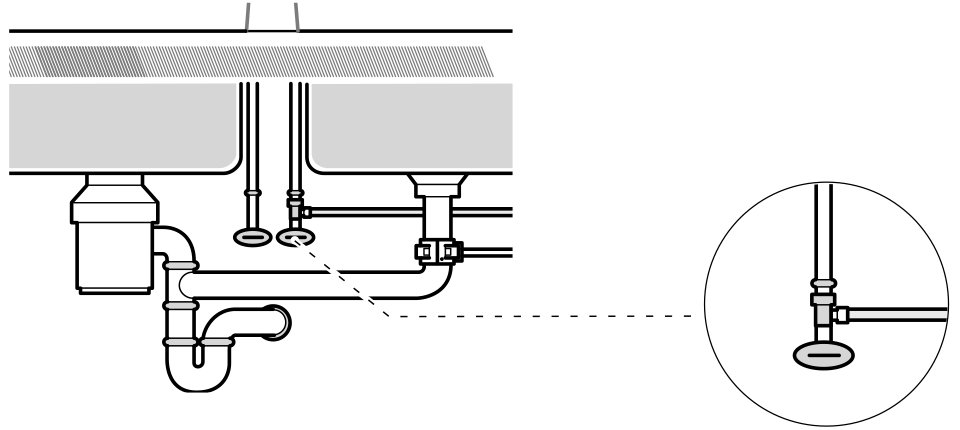
Drain Saddle
The drain saddle is used to create a wastewater connection to the drain under the sink. It is designed to fit a standard 1-1/2-inch OD drainpipe. The drain saddle must always be installed before (above) the P-trap and on the vertical or horizontal tailpiece.
Do not install the drain saddle near a garbage disposal to prevent debris from clogging the drain line.
Faucet Adapter & Ball Valve Shut-Off
The faucet adapter and ball valve shut-off are used to supply feed water to the RO unit and allow easy shutoff of the water supply when servicing the system.
SYSTEM AND FAUCET DIAGRAM

BEFORE INSTALLATION
⚠️ ALL GOVERNMENT CODES AND REGULATIONS GOVERNING THE INSTALLATION OF THESE DEVICES MUST BE OBSERVED.
Water Pressure Requirements:
60+ PSI is preferred for optimal RO filtering operation. 40 PSI is the minimum.
Options to Increase Water Pressure:
- For private well water sources: Adjust the pressure tank regulator, if applicable.
- Water Booster Pump: Installing a water booster pump may be an option to increase the water pressure. The booster pump can be installed in before feeding untreated water into the RO system. (Not included.)
When a Water Booster Pump May Be Required:
A booster pump (not included) increases the water pressure after filtering through the RO system. It is commonly required to properly deliver RO water in some installation scenarios. Typical scenarios, includes:
- Feeding multiple treated RO water lines from the RO system, and/ or
- The RO water delivery distance is greater than 20 feet from the RO system
- Located in a basement, or the ice maker is located across the room.
- If RO water is feeding the ice maker, and the it is sputtering, then a booster pump may be needed to increase the water pressure
INSTALLATION GUIDE
a. The RO filter system we come pre-assembled.
1. The advanced alkalizing filter or carbon block post-filter may need to be snapped into the top RO membrane filter. (see exploded diagram p.14) Please install now.


a. Locate the RO Faucet Location
(Under-sink cabinet or basement)
1. Requirements:
- Minimum of 2 inches of countertop clearance for the RO faucet mounting hardware.
- Combined countertop and sink thickness must not exceed 1.25 inches, or a faucet extension may be required (not included).
- If you have a granite, quartz, or stone countertop that may crack or split, or if the countertop is over 1 inch thick, consider hiring a professional to drill the faucet hole.
- Ensure the RO faucet can swivel freely and drain properly into the sink.
- Long tubing runs to feed an ice maker may require a delivery pump (not included).
2. Location Option:
As an alternative to drilling a new hole, an existing hole such as a sprayer or soap dispenser opening may be used to install the RO faucet.
b. Drill a New 1/2” Hole for the RO Faucet
Caution:
For granite, quartz, ceramic, or other countertop materials that may crack, chip, or scratch, consulting or hiring a professional is recommended. Always use the appropriate drill bits.
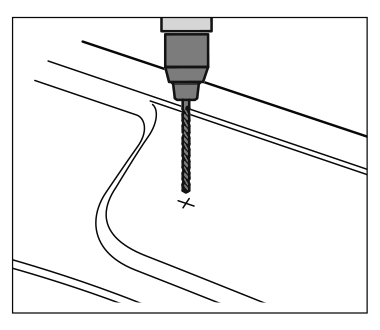
The following steps apply to stainless steel sinks only:
- Mark the center using a center punch for a 1/4” pilot hole.
- Drill the 1/4” pilot hole.
- Enlarge the hole to a 1/2” drill size.
- Deburr and clean any sharp edges around the sink opening.


c. Install the RO Faucet
- Assemble the RO faucet as shown.

- Insert the faucet assembly into the RO faucet hole from the top.
- Attach the washers and nut from the bottom.
- Attach the RO faucet tubing connector to the bottom of the threaded shank. Hand-tighten, then use a wrench to tighten an additional half turn only.

Tip:
It is best to have someone hold the faucet from above the sink to prevent movement during tightening.
If assistance is not available, tighten the hex nut until it is slightly less than fully tight. Then rotate the faucet base from above the sink, tightening it while positioning the faucet in the desired orientation.
1) Wrap Teflon tape around the threads on top of the tank.
i. Wrap Teflon tape clockwise around the thread 5–6 times.
2. Screw on a 1/4” tube valve. Hand tight only, do not overtighten.
i. Keep the storage tank valve in the OFF position.
3. Put the tank aside.

a) Shut-off the main cold-water supply
b) Turn on the sink faucet cold water to drain the remaining water.
c) Disconnect the cold-water sink faucet supply hose from the supply shut-off valve/ angle stop valve.
(Use a towel to catch any remaining water in the hose.)
NOTE: If an ice maker line already exists, then please remove or close this existing line. Later, you can tee into the new RO faucet line to supply filtered RO water to your ice maker.
d) Screw the 1/4” tube valve adapter onto the supply valve.
- Hand tighten and then use a wrench to tighten only another half of a turn.
e) Screw on the sink faucet hose to this 1/4” tube adapter valve.
- Hand tighten and then use a wrench to tighten only another half of a turn.


Flexible Riser Hose
Most riser hoses that are used today are made of flexible material, either braided stainless steel, braided plastic or gray 3/8” plastic tubing.
These flexible tubes are the easiest to use with the angle stop valve because the 2” of additional space needed for the faucet adaptor can be easily accommodated by flexing this kind of riser. A shorter riser hose will not be needed.
Copper Riser Tube
If your riser tube is made of copper you will need to either make a bend in the copper to allow for the 2” of space needed for the John Guest angle stop valve. If the copper tube is 3/8”, bending it can be done easily by hand.
The angle stop valve works with 3/8” shut-off valves and riser tubes. In some cases, older plumbing may use a larger size shut-off and riser tube.
In this case, it would be necessary to either replace the old valve and riser tube with new 3/8” parts, or use an alternative connection to draw the water supply to the reverse osmosis system.
Alternatives include self piercing valves, T-fittings, and faucet adaptors that connect between the faucet and the top of the riser tube.
Please consult your distributor or an installation professional for additional assistance

a. Locate and mark the drain saddle location. - Drain saddle must be located above the P-trap.
(Note: corroded pipes should first be replaced.)

b. Center and stick the black rubber gasket pad on the inside of the drain saddle hole.
c. Position the drain saddle hole to the new drainpipe hole and attach the drain saddle clamp unto the drainpipe
d. Drill a pilot hole into the tube opening of the drain saddle with 1/4” drill bit. Then enlarge the hole with a 3/8” bit.
Note: Only drill one side of the drainpipe. Do not drill through the other side of the drainpipe.

a) Place the two mounting panhead screws at least 15 inches above the floor and 7” apart from each other.
- Leave some space between the wall and screw head
- This is where the filter mount will sit.
b) Sit the RO filter assembly mount onto the two mounting screws

-
The 3/8” tubing is slightly larger than the 1/4” tubing and will only be used for this application.
-
Cut the appropriate tubing to length as needed while leaving enough slack for any future maintenance.
-
Color of tubing may vary.

a) Attach the black 1/4” drain tube from the drain saddle to the filter system
This is a gravity fed drain tubing line. This tubing should be placed in a direct path to the drainpipe without any loops, kinks or sharp bends. Cut this tubing as appropriate.
1. Start by loosening the compression nut on the drain saddle.
2. Insert the 1/4” tubing into this compression nut until it full seats
3. Hand-tighten the nut, and then use a wrench to tighten another 1-2 turns
b) Attach the yellow 1/4” tubing from the new 1/4” tubing supply valve to the inlet sediment filter
c) Attach the red 3/8” tubing from the alkalizing or carbon post-filter to the storage tank valve
d) Attach the blue 3/8” tubing from the RO faucet to the alkalizing or carbon post-filter filter
Note: If an ice maker line is to be supplied with this filtered RO water, Tee into the RO supply line. (These parts are not included.)
1. Cut this RO water supply line and insert 3/8” tubing tee
2. On the ice maker line side, add a 3/8” tubing valve
- Keep this valve in the closed position until the RO filter system is cleaned and ready for service
3. Then connect this RO water supply line to the ice maker line.
a. Shut-off the sink faucet
b. Turn-on the RO faucet.
c. Slowly turn-on the water supply valve.
d. Slowly turn-on the ¼” tubing supply valve adapter. Water will start running through the RO filter system and out of the RO faucet
e. Flush out the RO system by keeping the RO faucet.on for 3-4 minutes.
- Air and black carbon particles are common to flush out. This will stop once the system is fully flushed.
f. Check for leaks at this time and adjust as needed.
g. Shut-off the RO faucet after flushing the system.
h. Turn-on the storage tank valve
- Allow the system to produce RO filtered water and fill the storage tank (about 2hours)
Note: If an ice maker line was opted, please turn on the ice maker valve to supply the RO water to it.
Your RO filter system is now supplying the ice maker.
Optional and requires a T fitting and additional shut-off valve. Not supplied with RO unit.
The RO unit can be connected to any standard refrigerator ice maker or ice maker/water dispenser.
⚠️ Do not connect to a commercial type bar ice maker.
⚠️ Hooking up to existing copper tubing is not recommended due to possible corrosion.
To complete this operation, connect a T with a shut off valve into the faucet tubing and route tubing to the refrigerator.
Turn off the ice maker inside freezer prior to turning off the existing tap water supply line to the ice maker.
Turn on the icemaker after the RO system has been drained several times and the tank has a full supply of water.
Note: These additional parts are not included. The water flow rates with an RO filter system may decrease to an ice maker. The refrigerator may have the option to re-calibrate flow rate of the new incoming RO water feed.

Replacing Filters & Sanitizing The System
Each year the filters in the system should be replaced. Usually the membrane can be replaced every other year, but the prefilters and post-filter should be changed annually and in some cases more often.
Filter Replacement Steps:
1. Turn off the valve on the RO bladder tank.
2. Turn off feed water pressure.
3. Open RO faucet to relieve pressure.
4. Using the supplied housing wrench, remove the filter housing.
5. Discard old filters.
6. Clean filter housings with a cleaning brush.
7. Follow sanitizing steps in the “Sanitizing the System” section.
8. Install new filters in the system.
9. Remove and replace the GAC post filter. Remove fittings from old post filter, re-apply Teflon tape, and install fittings in new post filter.
10. Turn on feed pressure.
11. Open tank valve.
12. Allow water in the tank to flush out the post filter and run to drain until empty. Run 2 more complete batches to drain before using the water.
Membrane Replacement
1. Remove the supply tube from the end of the membrane housing that has only 1 tube.
2. Unthread the cap from the membrane housing.
3. Remove membrane using a pair of pliers.
4. Clean membrane housing with a brush.
Note: When installing a new membrane be sure to push the membrane into the housing as far as it will go. Each time the filters are replaced it is recommended that the system be sanitized.
Sanitizing the System
After all filters are removed from the system, housings have been cleaned, tank is empty, and faucet is open.
1. Add 1 gallon of water to a clean bucket.
2. Add 1 teaspoon of unscented household bleach.
3. Add 1 cup of this solution to each filter housing.
4. Tighten filter housings with solution on RO assembly.
5. Open tank valve and feed pressure valve.
6. Clean filter housings with a cleaning brush.
7. Allow water to fill the RO housing assembly until water comes out of faucet.
8. Close the faucet.
9. Allow water to run for 5 minutes.
10. Shut-off feed pressure.
11. Allow solution to stand for 30 minutes.
12. Open faucet and allow system to drain.
13. Remove water from housings before installing new filters and membrane.
14. Install new filters, tighten housings, and reconnect all tubing connections.
15. Open feed pressure valve and check for leaks.
16. Allow the system to make a full tank of water.
17. Run 2 cycles to drain to rinse out sanitizing solution before using water.
RO Systems are highly sensitive to pressure and temperature. RO Membranes always perform better under higher pressures. They produce more water, faster, and of better quality with high pressure. The vast majority of problems with RO Systems are a result of low pressure.
The effects of low pressure include water constantly running to the drain, slow water production, and low water volume available in the storage tank. In these cases where low pressure exists, a booster pump will be required.

On the following page is a table showing RO Membrane performance over a range of temperatures and pressures. Membranes are tested at 65 psi of pressure and temperature of 77 degrees.
For each incremental change in either variable, membrane performance changes accordingly. Higher pressures increase production and vice versa.


- Cold Water Line
- Angle Stop Valve
- Cold Water Shut-off Valve
- Melt Down Sediment Pre Filter
- Carbon Block Pre Filter
- Nipple
- Mounting Bracket
- Single Clip
- Automatic Shut-off Valve
- RO Membrane Housing
- Check Valve
- Tank Valve
- Double Clip
- Inline Granular Carbon Post Filter
- Drain Flow Restrictor
- Quick-Connect Faucet Connector
- Reverse Osmosis Water Faucet
- 1 1/2” Drain Pipe
- Drain Clamp
Locking clips are used on fittings where the tubing has a bend near the fitting.
Units come with plugs in the inlet, outlet and open end of T on the post-filter to create an air tight seal. Remove these plugs to perform the installation.